
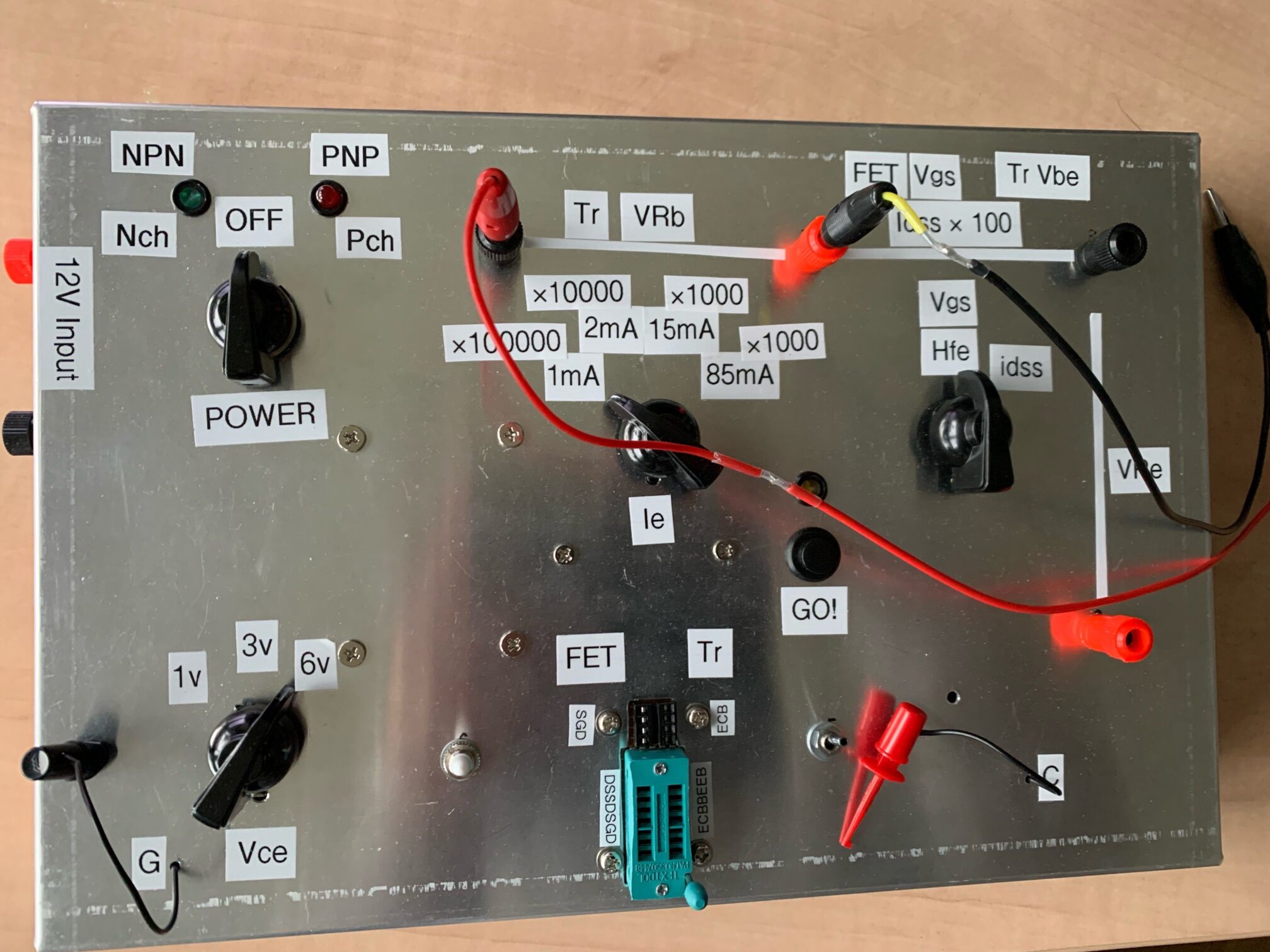
According to the cirduit design finished in below link, I have just finished assembly of Transistor/FET tester (hFE measurement device). It can fix the Emitter current (Source current) to measure hFE, Vgs, Vbe and IDSS, very versatile multi functional measurement device.
As I had increased the options, it required large panel area for many switches and selectors. Then I took out a cheapo aluminum thin box from my junk box which I bought ca. 45 years ago at Nihonbashi. The retro-looking nobs of selector were found in eBay, with minimum price in a bag. Many white tape indications are so bad looking, but I don’t care.
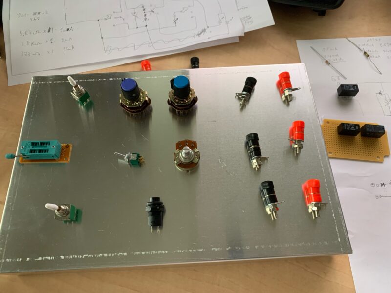
When the number of switches was defined, I put them on the case and considered the layout of them. Below initial idea was totally different to the finished design.
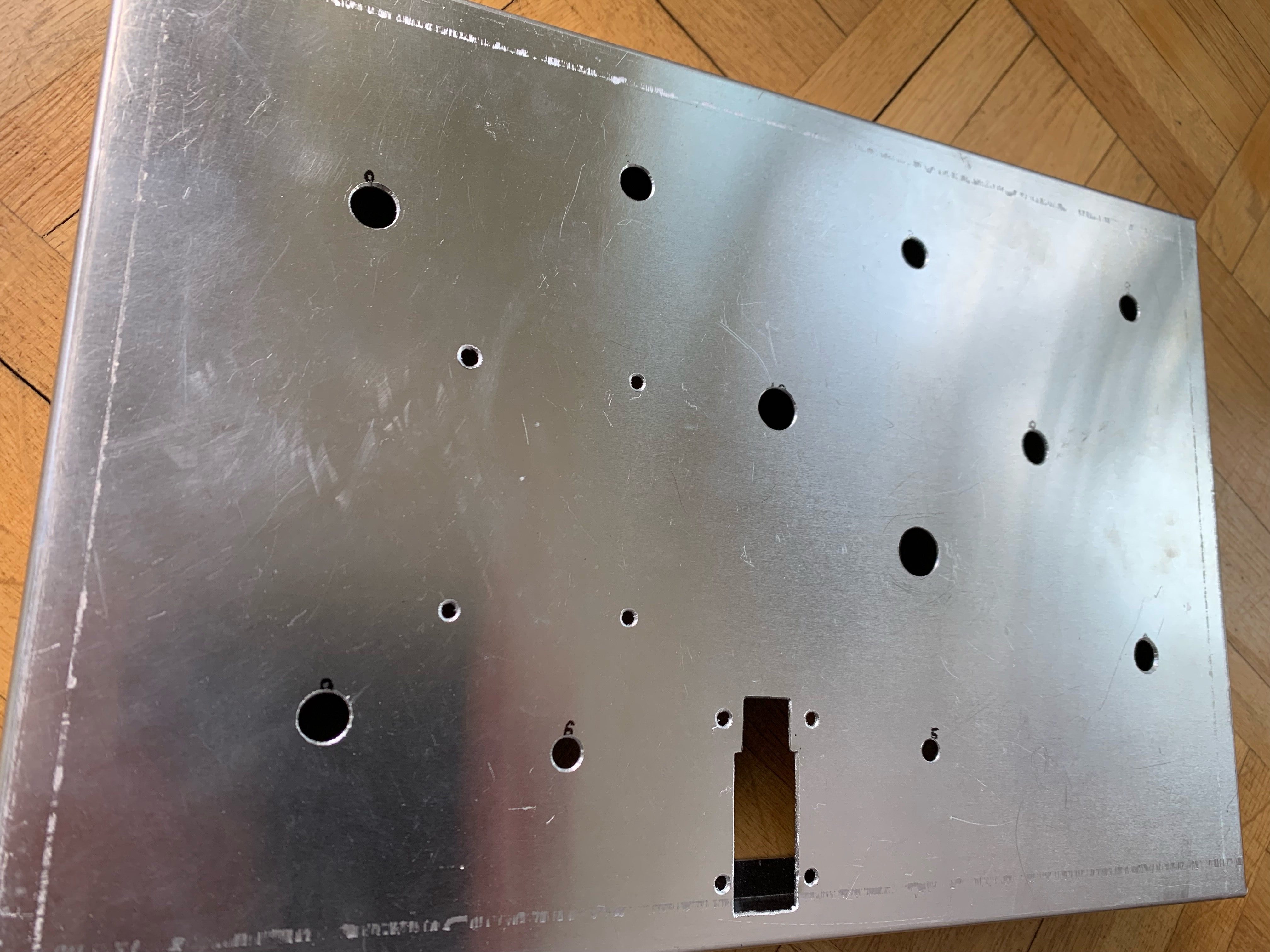
When the layout was completed, it just had to make many holes on aluminum. It’s not big work as I have luckily a table drilling machine. The connection of Transistor/FET is done with Zero Pressure Socket or DIP socket selectable. Manual filing work was therefore necessary.
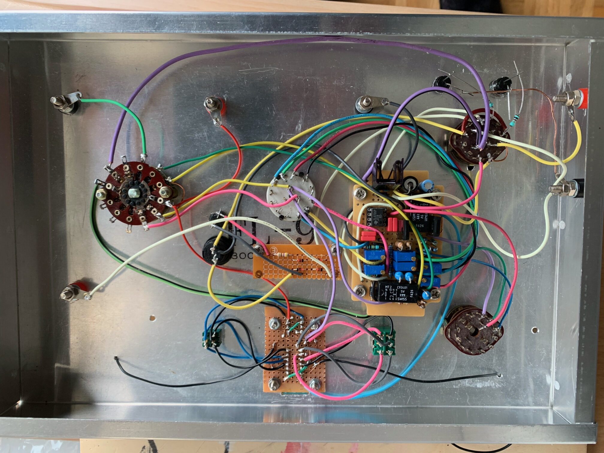
A picture right after the wiring completed. I worried about the connection condition of the Rotary switch from 40 years ago, but it was quite stable, Quality of ALPS, as it should be! The resistors were laid out standing up, forcing them into a small perforated board, and after I thought I had managed to do it, I realized I had forgotten the resistors for the LEDs on the panel, so I need them to be connected by Point2Point wiring. The measurement indicator LED needed a Di bridge to be lit by both positive and negative power supplies, so I was forced to add a small PCB as seen in the centre. Once done, the semi-fixed resistors are adjusted to match the emitter current and collector voltage to the values on the panel display.
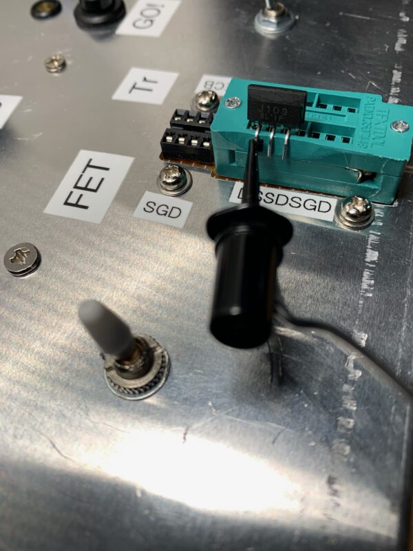
The socket pin-out is maniac so that dual-package transistors and FETs can be stuck straight in; the Gate of the FET (Collector of the transistor) is clipped in like this. Who cares the compatibility to Dual-package Tr in 2022 :-)? I DO!! The switch in the front selects the left or right element. When measuring power semi-conductors that do not match the pitch, a small alligator-clip cable with pins can be used.
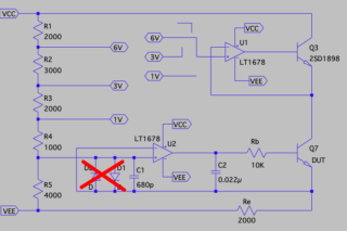
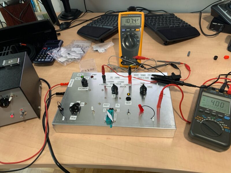
Thus, the 12 V supply is connected, the Emitter current is fixed at 2 mA and the Base current is measured. 107.4 mV is applied with a 10 k Ohm resistor, so 10.74 µA flows, which gives hFE = 186.2 = 2000/10.74. To be precise, as the Collector current is used as the numerator, it would be 187.2.
As you can see, the voltage at both ends of the Emitter resistor Re is monitored on the right side DMM and measured while checking that it is 4.00V. In fact, it was found that the 4V here was not stable as outcome of the resistor voltage divider and the feedback loop of the OP amplifier, so if it deviates from 4.00V, the voltage of the external power supply has to be manually adjusted from 12V, which is unfortunately a very troublesome process. The reasons are:
- The 4V setting of the resistive voltage divider is shifted by the DUT, etc. It is probably because the OP amplifier loop is in parallel to the 2k Ohm voltage setting resistor. Should I set the resistor value much lower so that it could be insensitive?
- Even when the DUT is included in the NF loop of the OP amplifier, it is not always possible to match the output voltage potential exactly to the input potential.
As I could not think of a solution to the first point immediately, I replaced the OP amplifier and measured the potential difference between input and output to counter the second point. I hesitated whether I could replace the OP amplifier with one that is not of single power supply specification, but since the input bias is 4 V, I thought it might be OK and gave it a try. It is interesting that when the Emitter current is switched, the behaviour changes depending on the type. Surprisingly, compared to the LT1078, which I ordered for this purpose as a high-precision OP amp, the 40-year-old 4558 had a smaller error.
| OP amplifier | 1 mA | 2 mA | 15 mA | |
| LT1078 | -40 | -65 | 0 | mV |
| OPA2134 | 0 | 0 | -270 | mV |
| uA4558 | -4 | -12 | -6 | mV |
| TL4558P | -10 | 0 | -110 | mV |
I replaced it with a uA4558 and started the sorting process, but a potential fluctuation of nearly 10 mV remained and it was not clear! I got mad, so I pulled out the single OP amp to dual conversion board and mobilised my treasured high-end OP amps.
| OP amplifier | 1mA | 2mA | 15 mA | 85 mA | |
| OP27 | 0 | 0 | +17 | +20 | mV |
| OP07 | 0 | 0 | +3 | +1 | mV |
| AD811 | +95 | +84 | +88 | mV | |
| CA3140 | +1 | +2 | +2000!! | mV | |
| AD797 | -1 | 0 | 0 | 0 | mV |
I have no complaint to the result of OP07 or AD797. When I examined it well, there seemed to be notes and know-how when using an op-amp for dual power supplies with a single power supply, and it seemed to be insufficient only to say that it was good or bad by replacing it at random.

Comment